

Operations
Engineering
Translate architectural intent into coordinated, buildable timber systems through structural engineering, DFMA, and material integration.
More Information
-
Past Projects
-
Technical Snapshot
-
Frequently Asked Questions
Deep Dives
-
Standards and Validation
-
Seismic Behavior of Engineered Timber Systems
-
Hybrid Interface Coordination
-
Common Engineering Assumption Failures
Introduction
-
Overview
-
Benefits
-
Woodlam's Engineering Approach
Overview
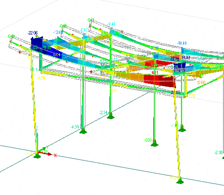
Engineering determines whether a timber structure can be manufactured and assembled as intended. Architectural drawings are translated into a project-specific structural basis covering load paths, serviceability, connection detailing, seismic requirements, and moisture-related movement before fabrication files are issued.
Unresolved assumptions can lead to redesign, approval delays, connection problems, and long-term serviceability issues. Early coordination reduces uncertainty across fabrication and installation.
Benefits
Buildable Structural Logic
Architectural geometry, long spans, cantilevers, and exposed structures are converted into calculated load paths, connection forces, and serviceability checks before fabrication begins.
Validate Against Standards
Structural systems are evaluated against the standards, authority requirements, and review process agreed for each project. Calculations and drawings are prepared for the agreed coordination and approval scope.
Integrate DFMA Early
Fabrication constraints, connector geometry, machining tolerances, and transport logic are resolved during engineering, reducing redesign during manufacturing and installation.
Coordinate Hybrid Systems
Timber-to-steel and timber-to-concrete interfaces are engineered early to control tolerance stacking, differential movement, and connection capacity.
Woodlam's Engineering Approach
Engineering converts architectural geometry into structural documentation through a defined calculation process. Each step resolves load paths, connection logic, and compliance benchmarks before fabrication.
Step 1: Translate Design Intent into Structural Logic
Engineering begins by analyzing architectural drawings and spatial ambition.
We review:
-
Load paths
-
Span requirements
-
Roof geometry
-
Exposure classification
-
Connection strategy
-
Seismic considerations
-
Moisture and movement behavior in tropical climates
Architectural design intent is converted into measurable structural parameters including load paths, cross section dimension sizing, serviceability limits, and connection design.
Output: Defined structural framework aligned to design intent.
Step 2: Integrate Material Performance Data
Material assumptions from Forestry are embedded into modeling.
Inputs include:
-
Density profiles
-
Durability class
-
Moisture behavior
-
Movement coefficients
Verified species data informs bending strength, shear capacity, deflection limits, and bearing conditions.
Structural modeling is based on measured timber properties, not generic assumptions.
Output: Climate-appropriate structural model grounded in verified material data.
Step 3: Model Structural Performance
Engineering evaluates the applicable load cases, member behavior, connections, serviceability, seismic requirements, and moisture-related movement for the project. Required checks and design criteria are defined before manufacturing coordination begins.
Output: Coordinated structural basis for manufacturing.
Step 4: Engineer for Manufacturing and Assembly
Structural design incorporates fabrication and installation constraints from the outset.
DFMA principles define:
-
Knock-down installation methods
-
Machining tolerances
-
Connector geometry
-
Grain-direction edge distances
-
Component sizing for transport
-
Interface coordination with steel and concrete
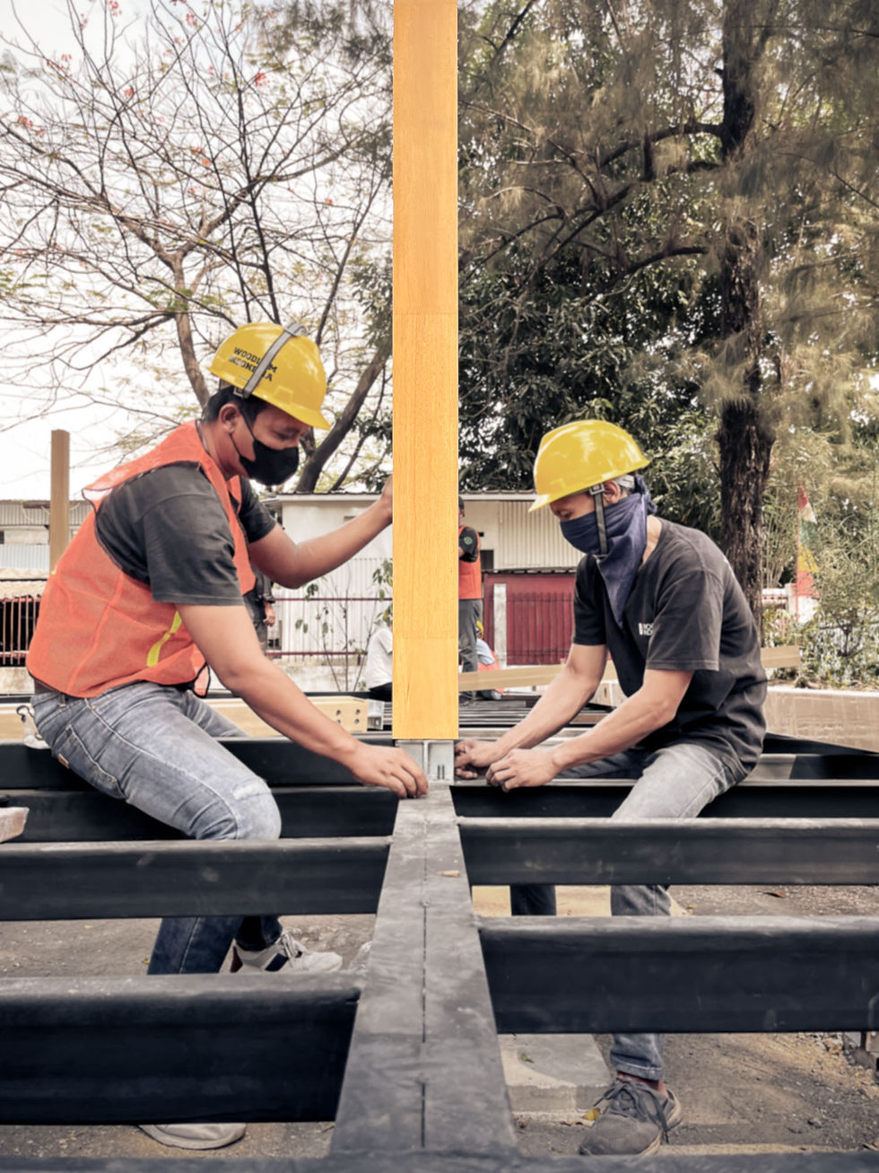
Engineering defines manufacturing constraints, component delivery constraints, and on-site installation constraints. Manufacturing does not correct structural assumptions.
Output: Fabrication-ready structural documentation aligned to assembly workflow.
Step 5: Issue Coordinated Project Documentation
Engineering outputs include:
-
Structural Analysis Report
-
Connector Design & Detailing
-
Component Fabrication Drawings
-
System Pre-cut/Machining Drawings
-
Installation sequence Drawings
-
Shop Drawings & Coordination
-
Bill of Materials (BOM) & Bill of Quantities (BOQ)
Packages support:
-
BOQ / Tender submission
-
Permitting review
-
Compliance validation
-
Investor due diligence
Material traceability from Forestry remains embedded within structural documentation.
Output: Submission-ready structural package with verified material continuity.
Standards and Validation
Structural integrity begins with a project-specific design basis. Applicable codes, material inputs, load cases, serviceability criteria, and responsibilities are agreed before calculations and fabrication coordination proceed.
Compliance requirements vary by location and project scope.
Without recognized modeling frameworks:
-
Span capacity may be overstated
-
Creep behavior underestimated
-
Building design not adjusted for harsh environments (like the tropics)
-
Serviceability limits exceeded
-
Connection performance mischaracterized
Engineering must be benchmarked against validated structural logic.
-
Material assumptions defined at the Forestry stage, including density, durability class, and moisture equilibrium, are embedded directly into structural modeling.
Standards are applied to verified inputs, not generic timber values.
This preserves traceability from sourcing to structural approval.
Proper validation reduces:
-
Structural miscalculation
-
Permit rejection
-
Tender disputes
-
Excessive deflection beyond serviceability limits
-
Long-term creep-related performance loss
Performance is modeled before fabrication. Not corrected on site.
-
Seismic Behavior of Engineered Timber Systems
In seismically active regions such as Indonesia, earthquake forces govern structural design.
Engineered timber offers reduced mass and ductile behavior, but seismic resilience depends on modeling connection designs, load distribution, and drift control during engineering.
Seismic performance is calculated through defined load combinations and behavior factors.
Seismic forces are proportional to structural mass.
Engineered timber structures are significantly lighter than comparable reinforced concrete systems. Lower mass reduces inertial forces acting on foundations and primary frames.
However, reduced mass alone is insufficient.
Connections are designed to perform in a controlled way under load, rather than failing suddenly. Energy is absorbed gradually through flexible behavior, not brittle breakage. This approach defines where movement is allowed and where strength must be maintained.
Glulam frames exhibit predictable behavior when modeled correctly.
Engineering evaluates:
-
Base shear relative to building mass
-
Moment-resisting frame action
-
Shear wall and diaphragm performance
-
Inter-story drift limits
-
Connection overstrength
-
Load redistribution pathways
Connection detailing governs seismic resilience. Brackets, hold-downs, and steel connectors are engineered to yield before primary timber members reach critical stress.
-
For projects in seismic regions, the applicable local code, performance criteria, connection strategy, and engineering responsibilities are established within the project design basis. These requirements are coordinated before fabrication files are issued.
Common seismic modeling failures include:
-
Underestimated base shear
-
Inadequate drift control
-
Incorrect connection overstrength
-
Brittle detailing at tension zones
Failures originate in modeling, not installation.
Engineering resolves these risks before manufacturing begins.
-
Hybrid Interface Coordination
Timber structures interface with concrete foundations, steel frames, facade systems, and cores.
These hybrid junctions require coordinated structural logic. Differential material behavior, tolerance stacking, and moisture response must be resolved in the engineering model.
Site coordination cannot resolve structural interface conflicts that were not addressed in the initial engineering processes.
Common coordination failures include:
-
Misaligned concrete, steel, and wood interfaces
-
Steel/aluminum brackets incompatible with timber edge distances
-
Incorrect finishing of steel/aluminum brackets
-
Unaccounted timber shrinkage and expansion
-
Cumulative tolerance stacking across trades
When interfaces are unresolved during engineering, site modification increases risk of structural failure.
-
Hybrid connections are engineered to accommodate:
-
Differential moisture and thermal movement
-
Material-specific load transfer behavior
-
Concealed and apparent connection design strategies
-
Defined installation tolerances
Timber moves with humidity cycles. Steel remains dimensionally stable. Concrete shrinks and creeps.
Interface detailing reconciles these behaviors within defined limits.
-
Engineering incorporates Design for Manufacturing and Assembly (DFMA) principles from the outset.
Structural documentation includes:
-
Machining tolerances
-
Connector geometry
-
Edge distances relative to grain direction
-
Component sizing for 6 m and 12 m transport
-
Cranage and lifting constraints
-
Installation sequencing logic
Complete structural elements, including beams, panels, floors, façades, and modules, are engineered for controlled off-site fabrication.
Manufacturing executes engineering. It does not correct it.
-
Engineering defines:
-
Transport-compatible component dimensions
-
Just-in-time delivery sequencing
-
Installation order relative to steel and concrete works
-
Temporary stability during phased erection
Prefabricated components and finished products are delivered within defined dimensional tolerances for controlled assembly.
-
When hybrid interfaces and DFMA constraints are resolved during engineering:
-
Concrete embeds align with connection detailing
-
Steel elements match structural schedules
-
Timber installs within defined tolerances
-
Rework on-site is reduced
-
Installation duration decreases relative to conventional wet construction
Execution reflects structural modeling because coordination was completed before fabrication.
-
Common Engineering Assumption Failures
Structural models are only as reliable as the assumptions they contain.
In timber engineering, incorrect assumptions often manifest later as excessive deflection, cracking, or connection distress.
Assumption control is central to reliable structural performance.
Timber is not dimensionally static.
In tropical climates, humidity cycles drive measurable movement.
If shrinkage and swelling coefficients are not embedded into modeling and analysis, engineers may underestimate:
-
Long-term deflection
-
Stress accumulation at restrained connections
-
Gap formation at interfaces
-
Finish distress
Species-specific movement data must inform the structural model.
-
Creep is the gradual increase in deflection under sustained load.
Misapplied creep factors can lead to:
-
Sagging beams beyond serviceability limits
-
Load redistribution into unintended elements
-
Perceived structural inadequacy
Creep modeling must reflect:
-
Species density
-
Moisture content
-
Load duration
-
Climate exposure
Long-term behavior is as critical as ultimate strength.
-
Connections are the most highly stressed components in timber structures.
Common modeling failures include:
-
Ignoring tension perpendicular to grain
-
Insufficient edge distances
-
Unrealistic fabrication tolerances
-
Inadequate fastener group analysis
-
Ignoring cumulative movement effects
Connection performance governs structural reliability.
-
Engineering uses verified inputs from Forestry, including:
-
Species-specific density
-
Durability classification
-
Moisture equilibrium
-
Movement coefficients
DFMA principles embed realistic fabrication tolerances.
Seismic and creep modeling follow recognized standards and tropical benchmarks.
Every structural assumption is validated before it becomes part of the model.
Performance is engineered through verified data.
-
Past Projects
Projects that prove structural calculation, geometry control, and timber behaving as an engineered material.

Kencana Valley – JSI Resort (2023)
Kencana Valley used curved Jabon glulam beams with radii as tight as 3,000 mm, with EN 14080 applied to the structural work. The project demonstrates controlled engineering and manufacturing for complex curved geometry.

Kencana Valley – JSI Resort (2023)
Kencana Valley used curved Jabon glulam beams with radii as tight as 3,000 mm, with EN 14080 applied to the structural work. The project demonstrates controlled engineering and manufacturing for complex curved geometry.

Kencana Valley – JSI Resort (2023)
Kencana Valley used curved Jabon glulam beams with radii as tight as 3,000 mm, with EN 14080 applied to the structural work. The project demonstrates controlled engineering and manufacturing for complex curved geometry.

Technical Snapshot
Project Design Basis
Applicable codes, authority requirements, and responsibilities
Structural Checks
Project-specific loads, member sizing, and serviceability criteria
Connection Coordination
Load transfer, interfaces, and buildability
Seismic Requirements
Criteria defined by project location and agreed scope
Moisture Movement
Species, exposure, and movement considered in detailing
DFMA Coordination
Machining files, connector schedules, and transport constraints
Documentation
Calculations and drawings prepared for the agreed review scope
Frequently Asked Questions
Got a question unanswered? Speak to Our Team.
Which Engineering Standards Apply?
The design basis is defined for each project according to its location, authority requirements, structural scope, and agreed review process. Confirm the required standards with Woodlam before design begins.
How Is DFMA Integrated into Engineering?
Engineering can incorporate manufacturing constraints, connector geometry, transport limits, and installation sequencing before production. The required DFMA scope is agreed for each project.
Can Woodlam Coordinate Timber, Steel, and Concrete?
Woodlam can coordinate timber interfaces with steel and concrete within the agreed engineering scope. Responsibilities, interfaces, and tolerances are defined with the wider project team before manufacturing.
What Engineering Documentation Can Woodlam Provide?
Documentation is prepared to suit the agreed project scope. Permitting, tender, or peer-review requirements must be confirmed at the start because local authority and consultant requirements vary.
How Are Seismic Requirements Addressed?
Seismic requirements are addressed within the project-specific design basis and coordinated with the appointed structural team. The applicable code, performance criteria, connection strategy, and responsibilities must be confirmed for each project.